Naval Architecture for RINA-Class Yacht Refit: Humpree Fins Foundation Design (2020 Van der Valk 94’)
- Jul 25, 2025
- 4 min read

When it comes to high-end yacht refits, the design of stabilization systems isn’t just about bolting hardware onto a hull. It’s about precision, foresight, and rock-solid naval engineering. In 2022, I had the opportunity to lead the full technical design of the foundation for Humphree electric fin stabilizers on a 94-foot Van der Valk yacht under RINA classification. This was no plug-and-play setup—every detail had to be custom-engineered.
Let’s dive deep into the full technical scope of this complex yet rewarding project.
Project Overview: From Concept to RINA Approval
The refit required the installation of two 1.5 m² Humphree full-electric servo fins. As the Naval Architect in charge, my responsibility covered the entire design and documentation workflow. This wasn’t just about meeting client expectations—it had to pass the scrutiny of RINA, one of the strictest classification societies in the yachting world.
Here's a breakdown of the full process:

1. Evaluation of the Installation Area
Before touching any modeling software, the first task was to assess the structural and spatial feasibility of the installation. We analyzed:
The optimal longitudinal and vertical positioning of the fins
Access limitations for welding operations inside tight hull compartments
Interferences with adjacent structures: furniture, floor systems, tanks, and existing bulkheads
Access turned out to be one of the trickiest parts. Creating enough space for future welding and maintenance operations meant redesigning internal partitions and ensuring safe working zones inside the yacht’s bilge.
2. 3D Scanning and Integration with Existing Structure
A detailed 3D scan of the installation zone was carried out to ensure millimetric precision. Using Rhinoceros 3D, I merged the scan data with the yacht’s structural plans, enabling:
Real-time collision checks with structural and interior elements
Accurate modeling of the hull curvature for fin cutouts
Identification of space constraints for equipment installation and access routes
This step was vital for predicting how the foundation would integrate with the existing hull geometry and systems layout.
3. Design of the Watertight Foundation Structure
Next came the core of the engineering challenge: designing a watertight foundation (cofferdam) for the Humpree system that:
Matched the hull angle to ensure proper fin deployment and performance
Provided enough stiffness for the forces exerted by the stabilizers during operation
Respected RINA’s structural criteria for reinforcements, material compatibility, and welding practices
Since the Van der Valk 94’ yacht is built entirely in marine-grade aluminum, the entire foundation had to be designed using marine-grade aluminum alloy (typically 5083-H116). This introduced unique challenges, including:
Ensuring all reinforcement elements were compatible with the aluminum hull structure
Adapting weld procedures to aluminum standards to avoid heat distortion and preserve watertight integrity
Minimizing galvanic corrosion risks by isolating dissimilar metals in the stabilizer housing
Using Rhinoceros as the base model, I performed a Finite Element Analysis (FEA) on the aluminum foundation structure to validate its performance under operational loads. The FEA simulation enabled:
Realistic load simulations from fin operation in various sea states
Identification of local stress concentrations and potential fatigue zones
Optimization of weld bead locations, material thicknesses, and stiffener placement specific to aluminum behavior under cyclic loading
The final design was a custom-fabricated aluminum cofferdam, integrated with existing hull frames and longi supports, reinforced where needed, and fully modeled and stress-tested before shop fabrication.

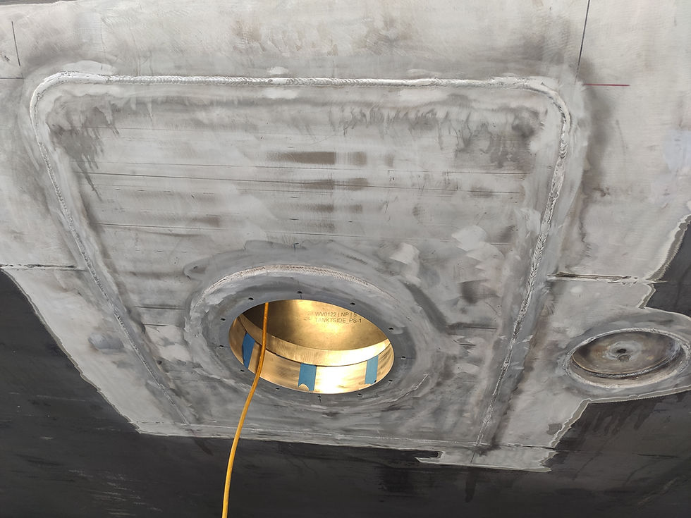
4. Hull Cutout and Fin Positioning
Once the foundation design was validated structurally and approved internally, the next step was calculating the exact hull cutout:
The hull was pierced precisely to match the fin root and servo shaft
A bevelled cut was modeled in Rhino to allow flush welding of the fin mount
We maintained alignment with RINA guidelines for minimum distances from structural reinforcements
The angle of the fins was carefully studied to optimize both roll-reduction performance and hydrodynamic flow, especially during low-speed cruising and anchoring.
5. Routing and Deployment of Internal Equipment
Installing the full-electric servo units required meticulous planning:
Routing paths for power cables, control lines, and hydraulic backup systems
Temporary removal of interior furniture and raised floors
Access hatches designed into adjacent panels for future servicing
Every move inside the yacht was calculated—not just to place the hardware, but to do it without compromising interior aesthetics or structural integrity.
6. Construction Drawings and Documentation
Once the design was locked in and validated through FEA, I prepared the full construction documentation, including:
General Arrangement and Detail Plans (foundation geometry, reinforcement layout)
Welding and material specifications
Fin installation sequencing
Sectional views showing system integration with the hull
Interference maps for onboard routing
These drawings were compiled into a technical dossier tailored for RINA review and shipyard use.

7. Submission to RINA and Class Approval
Perhaps the most critical milestone was the submission to RINA for structural verification and class approval. All documentation had to:
Match RINA’s latest yacht classification rules
Include structural calculations supported by the FEA model
Show compliance with watertight integrity and hull reinforcement standards
Following some minor clarifications, the entire package was approved—allowing us to move forward with manufacturing and installation.
Lessons Learned and Professional Recommendations
Based on this case, here are some key takeaways for professionals involved in stabilizer retrofits:
Start with access: Plan not only the design but the reality of how the crew or technicians will work within the tight compartments of a yacht.
Use 3D scans early: Integrating real geometry saves weeks of clashes and last-minute changes.
Run FEA on every critical component: Especially on custom foundations—manual calculations aren't enough for class approvals.
Balance structure with systems: Reinforcements are key, but they must coexist with tanks, cable trays, and interior finishings.
Communicate with classification bodies early: Involving RINA or similar societies early in the design avoids rework and delays.
Document everything: Even the smallest changes in fin position or hull cutout should be documented for warranty and future upgrades.
Final Thoughts: Pushing Naval Architecture Forward
This project showcased how deep technical skill, simulation tools like FEA, and hands-on experience come together in high-end yacht refits. It wasn’t just about installing a fin system—it was about integrating a critical performance component into an existing luxury structure, without compromising safety, aesthetics, or class certification.
For anyone looking into "yacht refit services" or needing certified work involving Humpree systems and RINA compliance, this type of process sets the bar for excellence.


Comments